
Scan-driven engineering reduced retrofit uncertainty, improved material flow, and supported first-time field fit-up in a complex power generation facility.
Industry: Power Generation
Facility Type: Coal-fired power generation facility
Application: Coal handling / crusher feed system
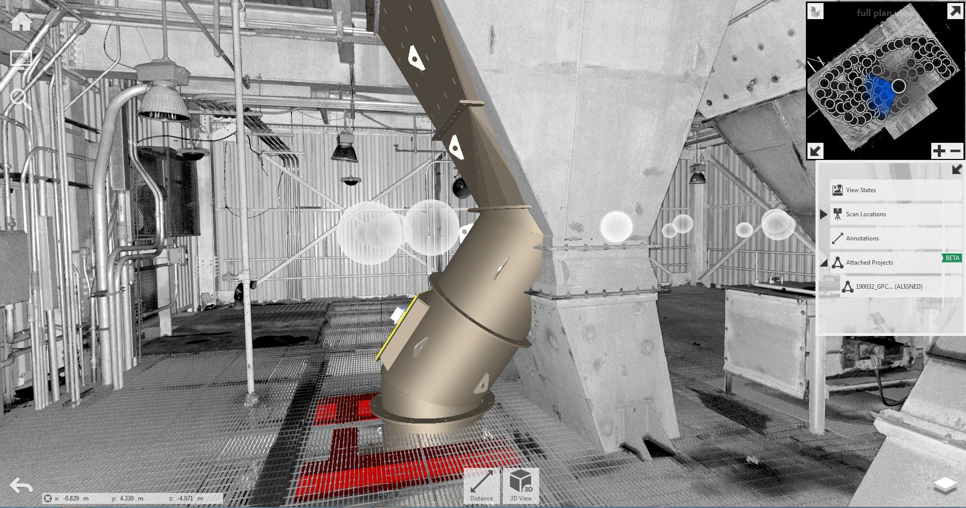
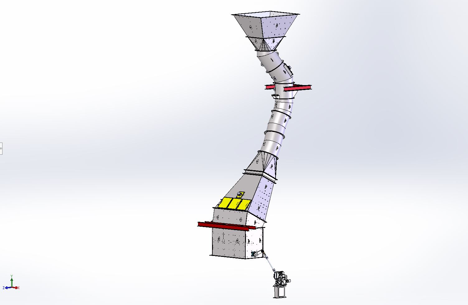
Project Scope: Conveyor head chute to crusher retrofit
Services: 3D laser scanning, 3D modeling, DEM simulation, retrofit engineering support
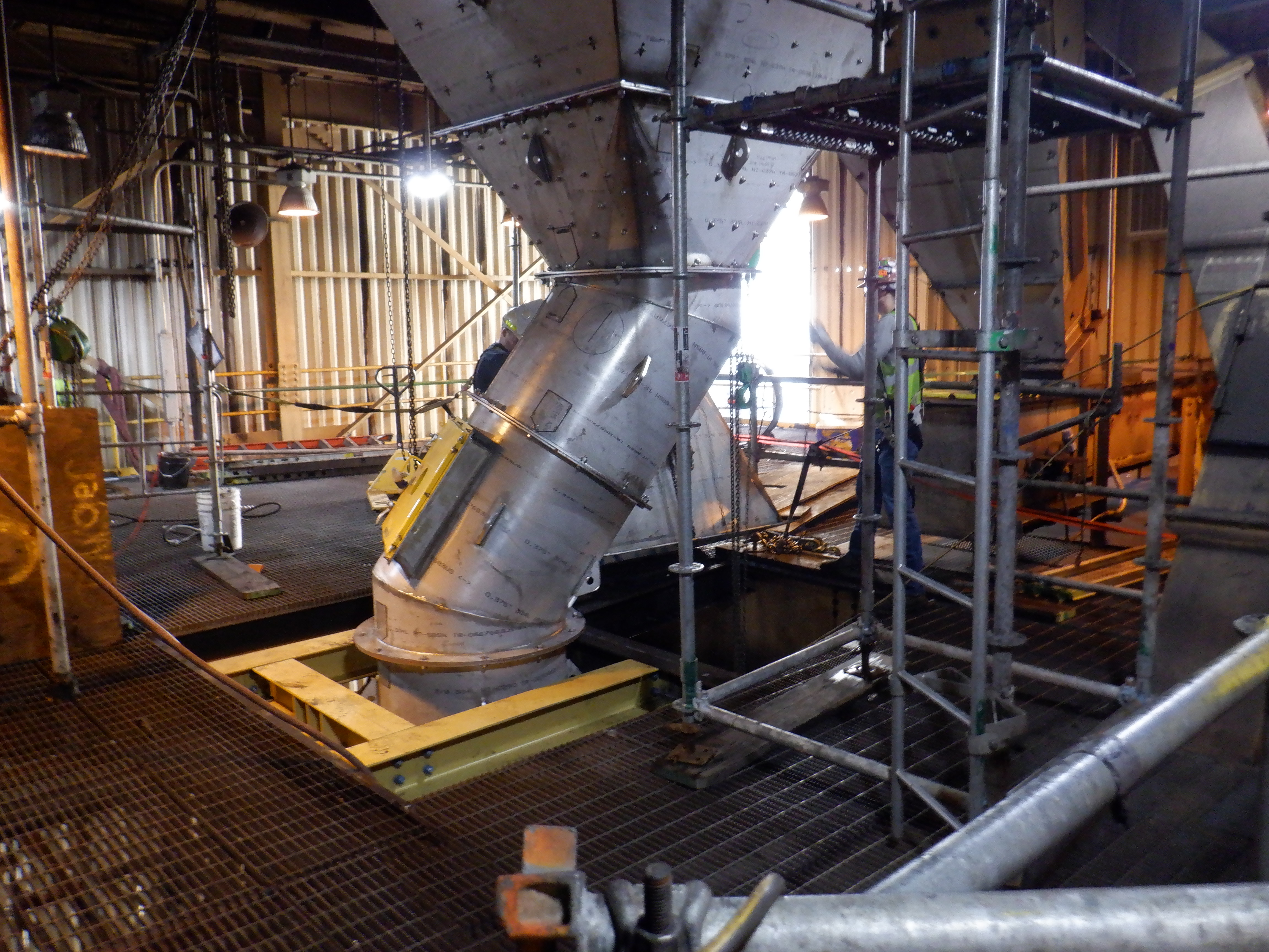
A power generation facility needed to replace and improve a critical crusher feed chute inside an existing coal handling system.
The project was not a simple like-for-like replacement. The retrofit had to fit within a congested existing structure, connect to field conditions that were difficult to measure manually, and improve how material loaded the crusher.
The team needed a retrofit that would install correctly the first time, reduce outage risk, and improve how material moved through the transfer chute.
To reduce uncertainty, the project used a scan-driven engineering workflow that combined laser scanning, 3D modeling, DEM simulation, and final alignment checks before delivery.
The existing chute system created two key challenges.
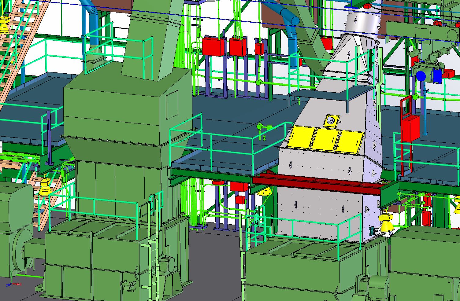
First, the retrofit had to physically fit within a dense brownfield environment. Existing structural steel, grating, equipment, platforms, and chute work limited routing options and created tight installation tolerances.
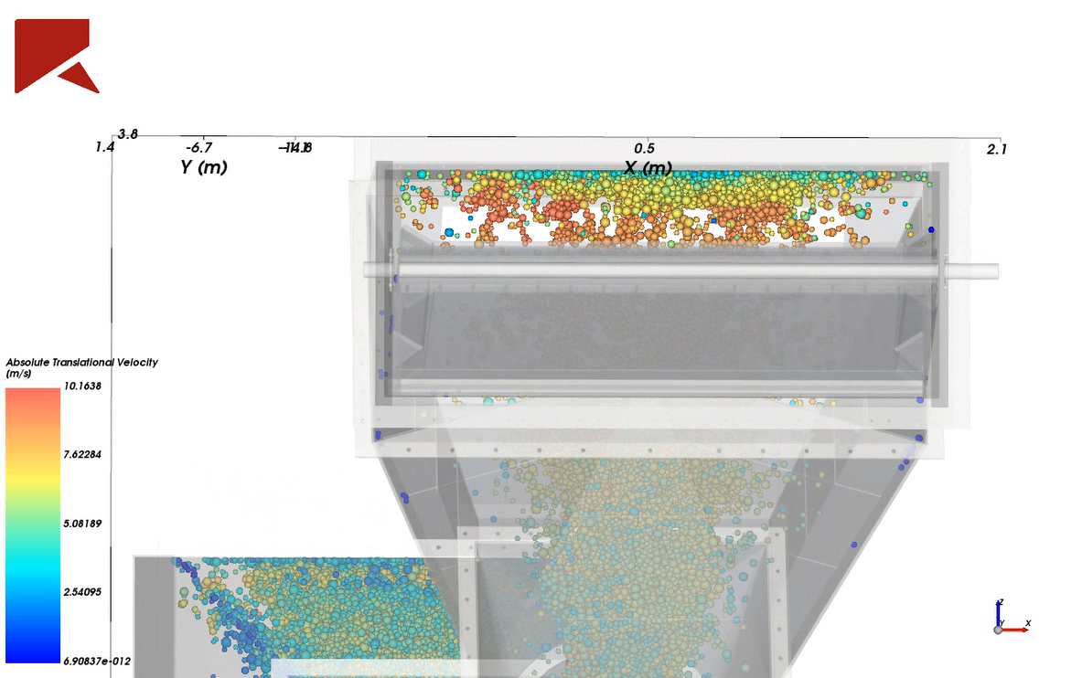
Second, the retrofit needed to improve material flow. The existing chute path contributed to uneven material loading across the crusher rotor. Uneven loading can concentrate wear, shorten rotor life, and increase maintenance exposure.
The team needed to validate both fit-up and performance before the outage window.
Key project constraints included:
The retrofit had to fit the first time and perform better than the system it replaced.
The existing crusher house created a highly constrained retrofit environment.
The new chute system had to connect to existing equipment, maintain proper alignment, route through existing structural steel, preserve clearances, and land correctly at each connection point.
For segmented chute work, small dimensional errors can compound across the assembly. Flange orientation, bolt-hole alignment, chute routing, and support geometry all had to work together for the system to install in the intended field position.
Primary engineering constraints included:
These conditions made it critical to validate the retrofit before fabrication and installation began.
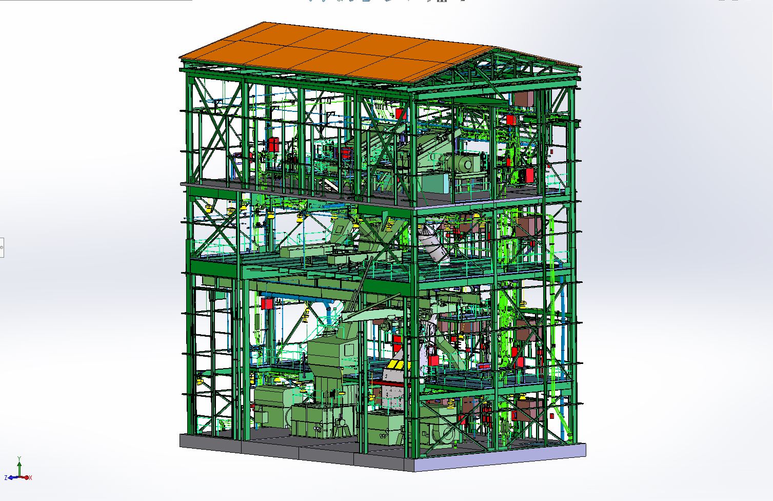
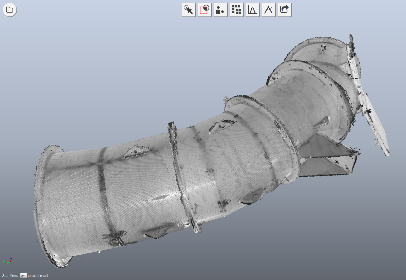
AsBuilt created a high-fidelity digital foundation using industrial laser scanning and 3D modeling.
Laser scan data captured the existing conditions, including structural steel, surrounding equipment, chute geometry, tie-in points, and field clearances. The scan was then used to develop and coordinate the retrofit model against real facility conditions.
This digital engineering workflow enabled the team to:
This approach moved project risk upstream, allowing the team to resolve design and coordination issues before the outage began.
Laser scanning provided the accurate existing-conditions data required for the retrofit.
The scan captured critical dimensions that could not be reliably measured by hand, including tie-in geometry, clearances, structural conditions, and routing constraints.
The 3D model was then used to coordinate the retrofit against the real-world environment. This helped the project team isolate the new design, review it in context, and verify that the chute route and support steel would fit before field installation.
The scan and model supported:
For complex industrial facilities, this type of scan-based modeling helps replace assumptions with verified field data. See more examples of industrial scan and modeling projects.
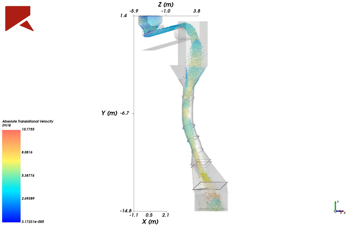
DEM simulation was used to evaluate how wet coal would move through the redesigned chute path at approximately 1,400 tons per hour.
The goal was not only to make the new chute fit. The design also needed to improve material behavior through the transfer.
The DEM simulation helped validate that material would remain sliding through the chute instead of freefalling. This mattered for several reasons:
The redesigned chute geometry helped center and spread material more evenly across the crusher rotor, supporting improved reliability and longer equipment life.
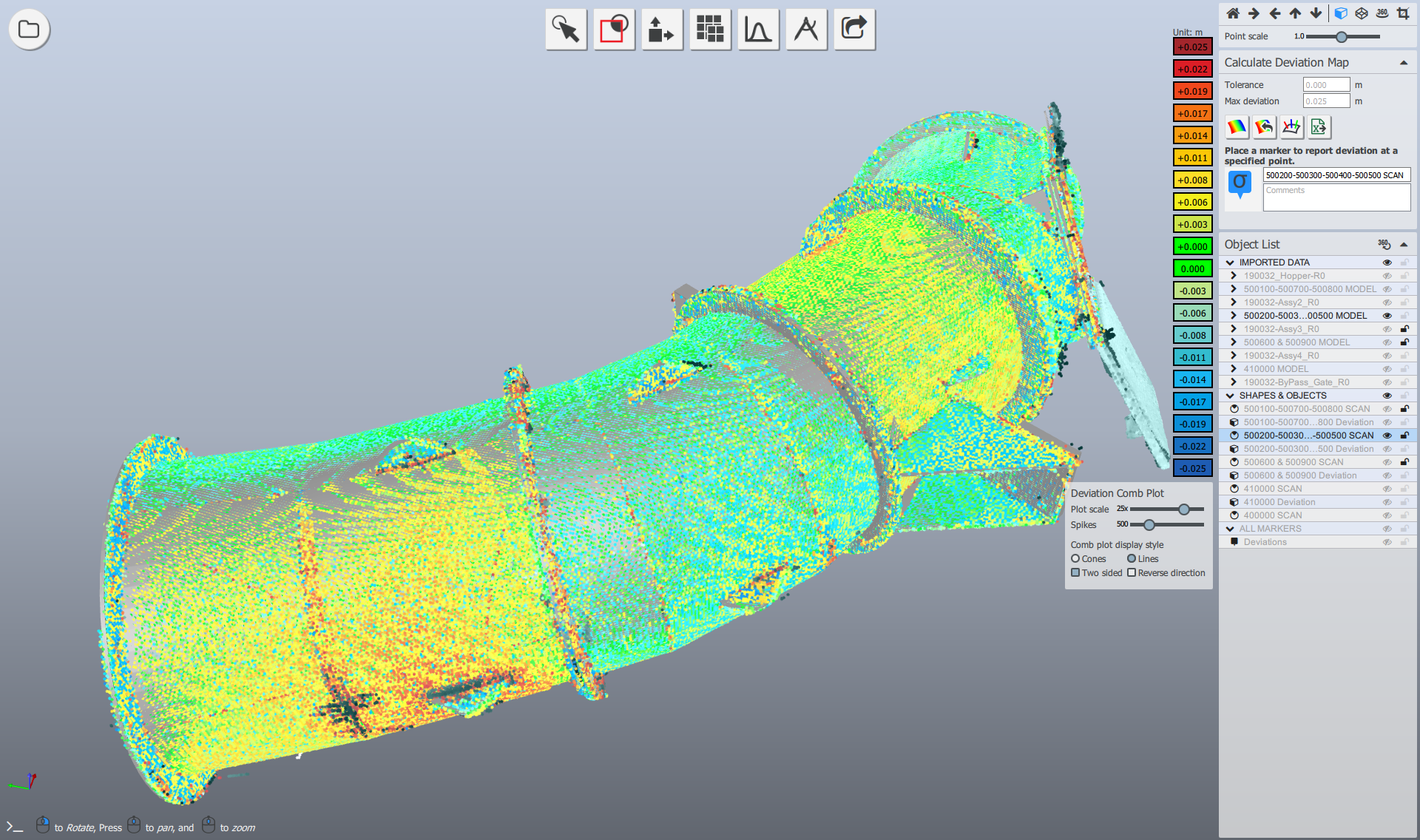
As a final quality control step, fabricated chute sections were checked against the 3D model before delivery.
The purpose was not to create a separate fabrication study. It was to confirm that the components most critical to field assembly matched the design intent before they reached the site.
This included checking:
For segmented chute work, small dimensional errors can compound across the system. A flange can have the correct bolt pattern and still create fit-up issues if its rotational orientation is off.
By checking fabrication alignment before shipment, the team reduced the risk of discovering fit-up issues during the outage window.
Existing flange geometry, chute routing, and key connection points were validated before installation.
Wet coal flow was simulated through the redesigned chute to validate sliding material transfer and crusher loading behavior.
The redesigned chute helped spread material more evenly across the crusher inlet, reducing concentrated rotor wear.
Routing, clearances, tie-ins, and support steel were coordinated before the outage.
Access features and a replace-in-kind bypass gate supported inspection, maintenance, and long-term operations.
Industrial retrofits are often constrained by incomplete drawings, undocumented changes, tight clearances, and short outage windows.
This project demonstrates how scan-based engineering and DEM simulation reduce risk in complex retrofit execution.
Execution shifted from field uncertainty to controlled, scan-driven retrofit delivery.
Scan-driven engineering helped de-risk the retrofit while improving crusher loading performance.
By combining 3D laser scanning, 3D modeling, DEM simulation, and final alignment checks, the project team reduced installation uncertainty and improved long-term operating performance.
No field guesswork. Better flow. Predictable installation.
AsBuilt helps project teams capture accurate field conditions, build design-ready models, and reduce uncertainty before construction or outage execution begins.
Explore our 3D laser scanning and modeling services, view more project examples, or request a quote.
Talk with our team about your facility, scope, and objectives to determine the right capture, modeling, and analysis approach.