
A bulk material handling project should not move from outdated drawings straight into fabrication.
There is too much risk between those two points.
The existing structure may not match the legacy drawings. Preferred components may not be integrated correctly. Chute geometry may not solve the actual operating problem. A fabrication package may leave too much to interpretation. And the installation contractor may still be forced to solve fit-up, sequencing, and access issues inside the outage window.
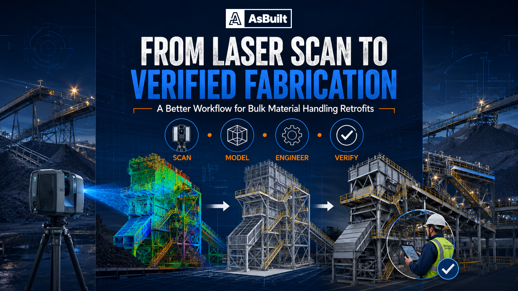
A better bulk material handling retrofit workflow starts earlier and stays grounded in reality all the way through fabrication and installation planning.
That is the advantage of a field-verified approach.
Instead of starting with assumptions, the team starts by defining what the project must accomplish. Then it captures the actual plant environment with 3D laser scanning, builds the as-built model, engineers the retrofit around real constraints, validates flow behavior where needed, produces a fabrication package, verifies fabrication before delivery, and supports installation planning before shutdown work begins.
For owners and project teams, that means more control over design intent, better bid quality, fewer field surprises, and higher confidence before fabrication dollars are committed.
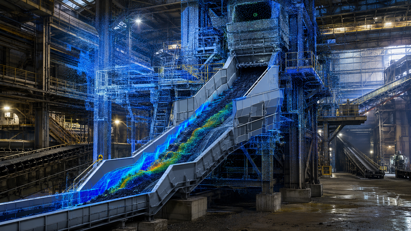
In a mission-critical coal transfer tower retrofit, this workflow supported a six-floor transfer tower redesign handling up to 6,400 tons per hour, with outage exposure estimated at up to $10,000 per minute. The team used laser scanning, 3D engineering, Rocky DEM simulation, and scan-verified fabrication to reduce risk before installation.
In bulk material handling, retrofit risk rarely begins in the fab shop. It usually begins at the starting point.
When teams rely on outdated drawings, partial redlines, or undocumented field changes, they create downstream problems that show up at the worst possible time. Support steel is not where the drawing says it is. Existing chutes have been modified. Clearances are tighter than expected. Access paths are not practical. Demo assumptions do not match reality.
That is why a better workflow starts with accurate existing conditions and a field-verified basis for engineering. Instead of asking contractors and fabricators to solve problems in the field, the project team works from reality from the start.
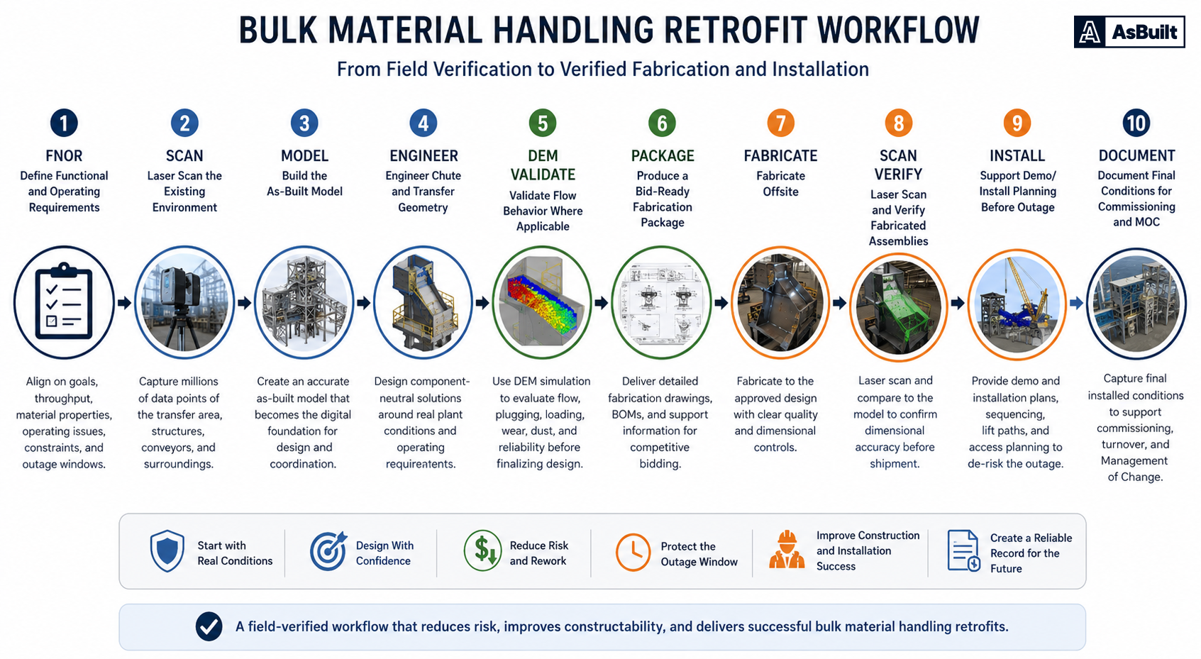
Before design begins, the team needs a clear definition of what success looks like.
That starts with the Functional and Operating Requirements. The FNOR should define throughput, material behavior, current operating failures, wear concerns, dust issues, outage constraints, maintainability expectations, and the real operating problem the retrofit needs to solve.
This matters because a retrofit should not be driven by a preferred product alone. It should be driven by the plant’s actual requirements.
When the FNOR is clear, the team can evaluate design decisions against real operating goals rather than assumptions.
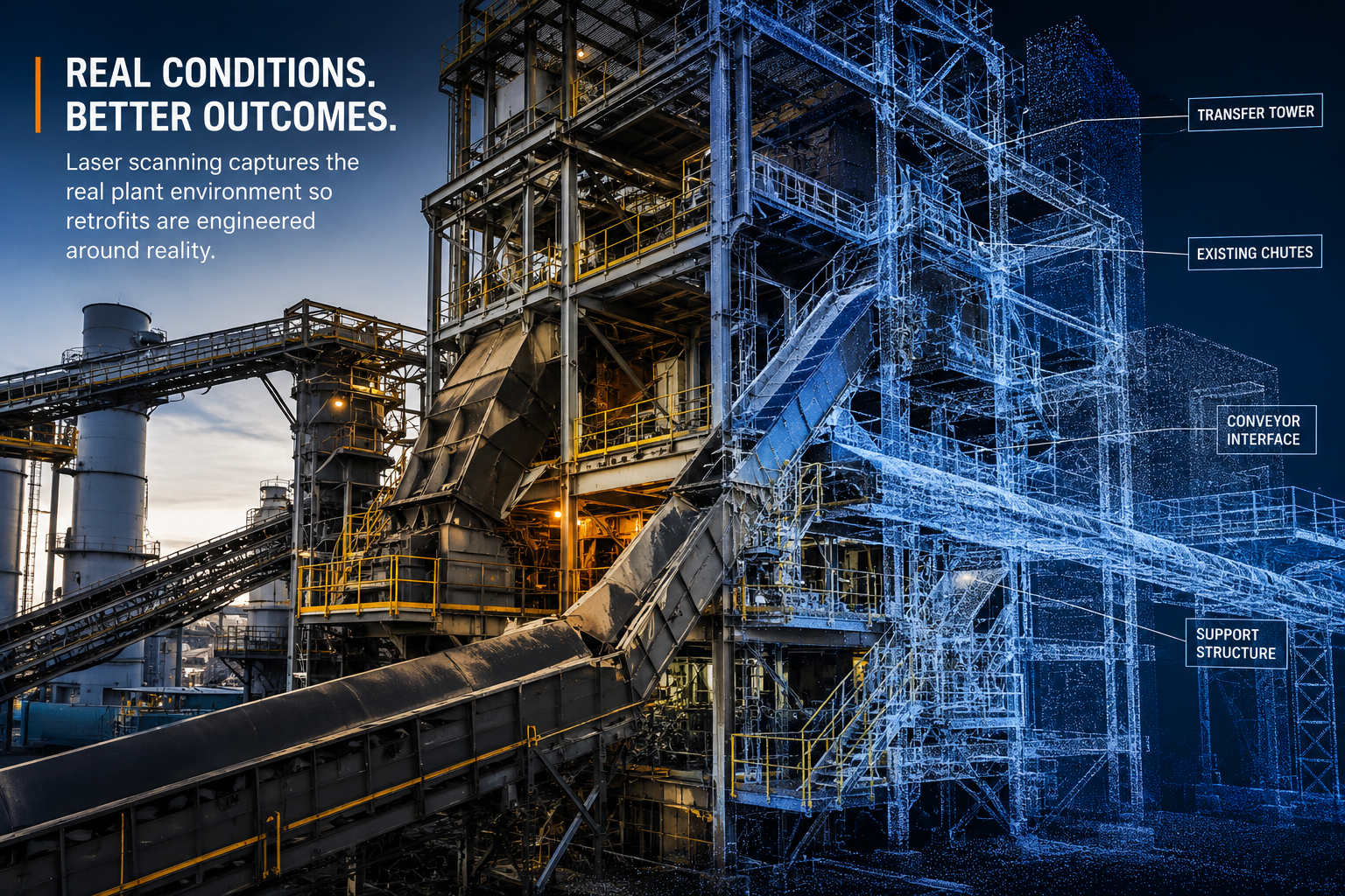
Once the requirements are defined, the next step is to capture the real field conditions with 3D laser scanning.
This is critical because industrial facilities change over time, and legacy drawings often stop reflecting reality. For bulk material handling retrofits, this may include transfer towers, conveyors, chute interfaces, support steel, surrounding equipment, access ways, and adjacent systems that affect fit, installation, or demolition planning.
Laser scanning replaces assumption with measurable reality.
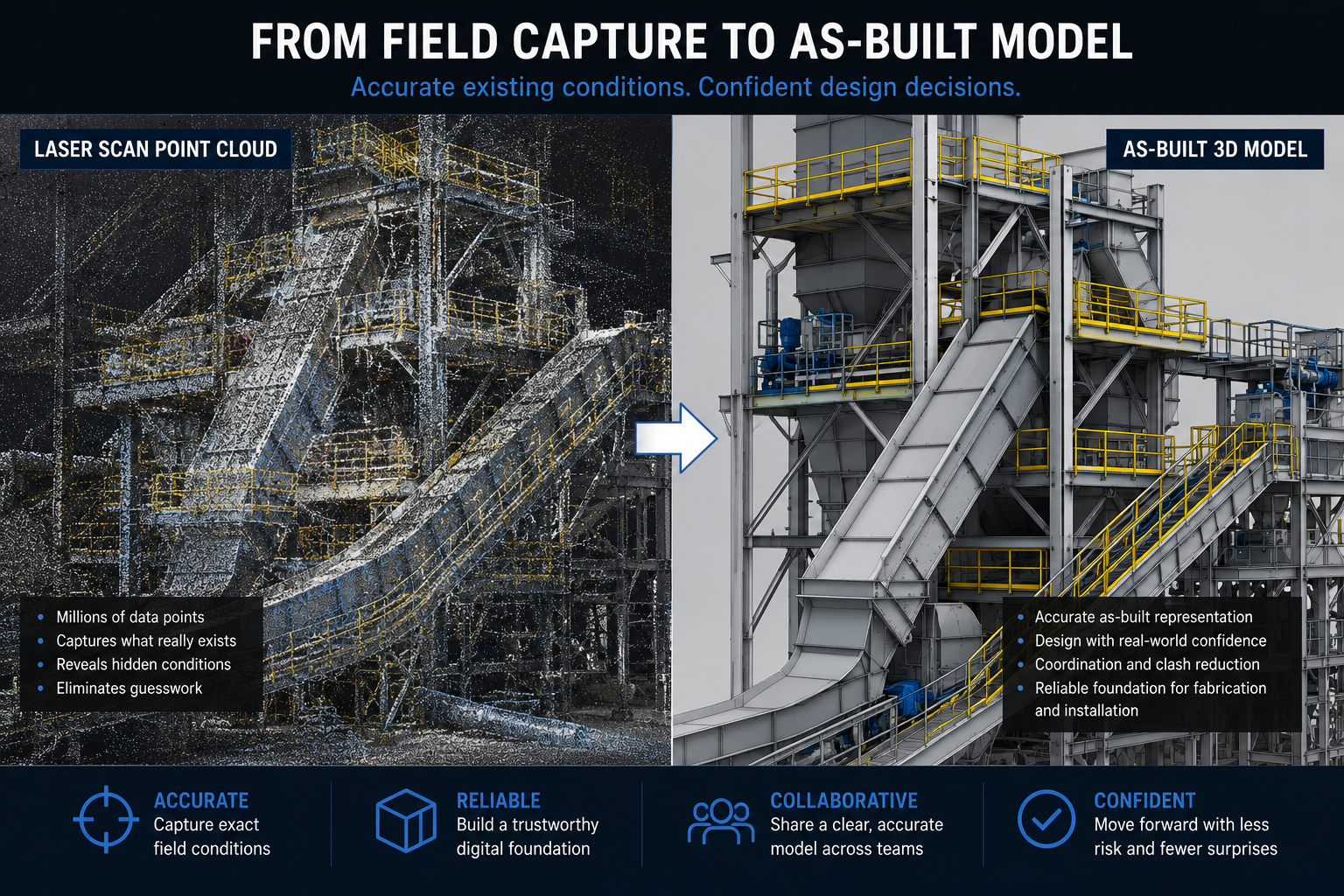
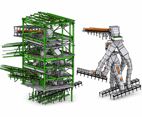
Scan data becomes useful when it is turned into a usable as-built model.
That model gives the team a field-verified digital environment for engineering, coordination, and planning. Instead of designing in abstraction, the team is designing around the actual plant.
This is where the project begins to de-risk in a measurable way. The same model can support coordination, fit review, constructability, and downstream verification work.
With the as-built model in place, the retrofit can be engineered around real constraints.
This is especially important in bulk material handling because transfer performance depends on how the chute, conveyor geometry, loading trajectory, support conditions, wear zones, and maintenance access all work together.
For that reason, the most effective approach is often component-neutral. The owner gets a design package built around plant requirements and field conditions, not just a product preference.
That gives owners more flexibility in vendor selection and more control over procurement.
Not every project needs DEM, but when flow behavior is complex or failure consequences are high, simulation can meaningfully reduce risk.
For transfer points, DEM-supported review may help teams evaluate plugging risk, loading behavior, wear exposure, dust generation, and maintainability before fabrication begins.
When used correctly, DEM strengthens engineering judgment and helps teams identify issues earlier, when changes are still easier and less expensive to make.
Once the retrofit concept is engineered, it still has to fit the real plant.
This is where scan-based analysis and verification becomes valuable. Because the model is tied to field conditions, teams can review support points, surrounding steel, tie-ins, maintenance access, and likely interferences before the work reaches the outage window.
That reduces RFIs, field rework, and installation surprises.
A bulk material retrofit should not end with a concept model.
It should move into a fabrication package that can be priced, reviewed, and built with confidence.
A field-verified package gives owners more control over procurement because fabricators are bidding against a defined scope instead of interpreting incomplete intent. That is especially valuable for transfer chute fabrication drawings, conveyor retrofit design packages, and outage-driven work where ambiguity becomes expensive.
One of the strongest advantages of this workflow is that it does not stop at engineering.
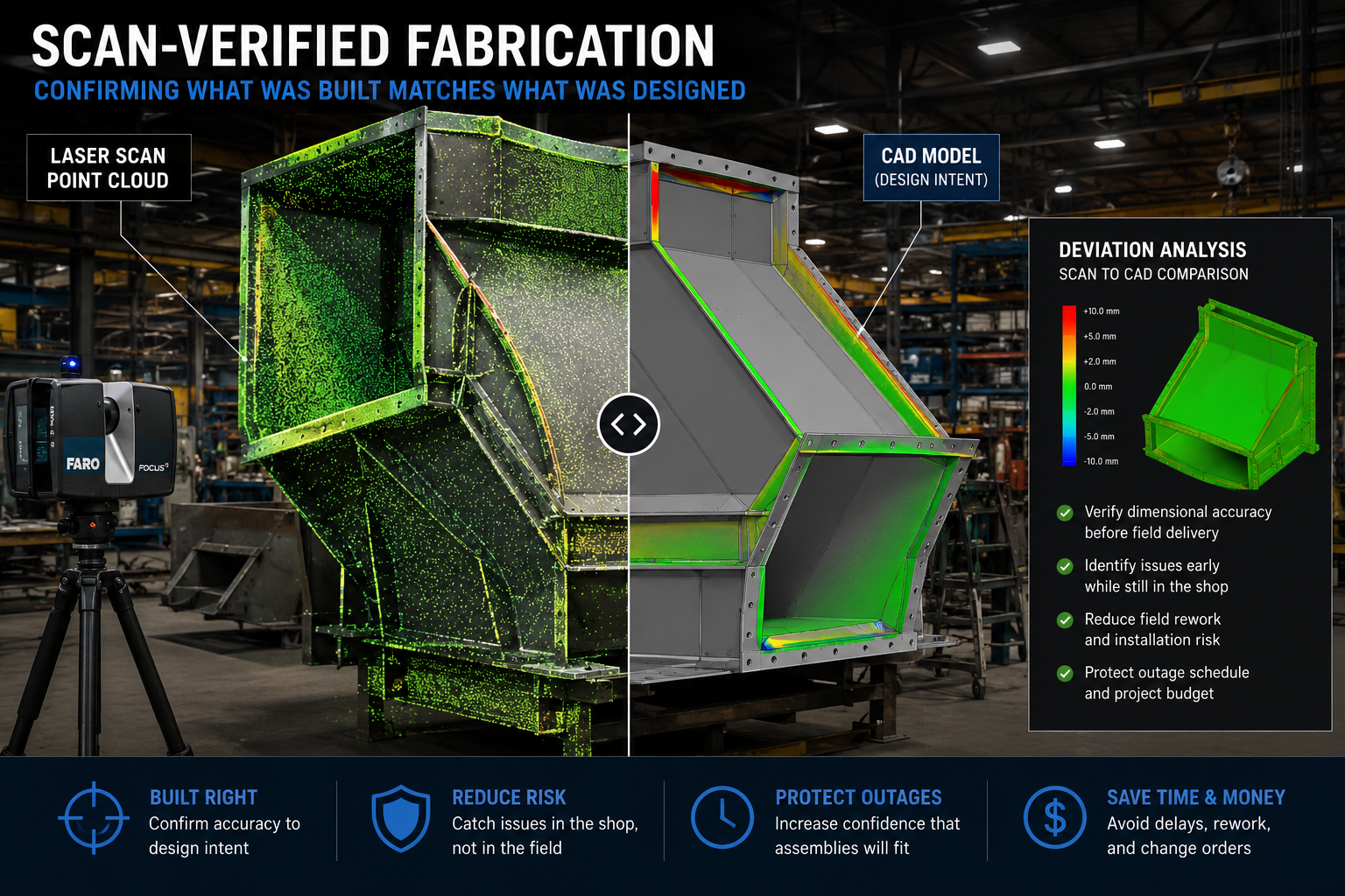
Before fabricated assemblies ship, they can be checked against the model using fabrication and installation verification.
For shutdown-driven projects, that is a major advantage. It is far better to catch a dimensional issue in the shop than in a transfer tower during an outage.
Scan-verified fabrication helps protect the installation window and increases confidence that what was built matches what was designed.
Even a well-engineered retrofit can struggle if the installation team does not have a clear plan.
That is why this workflow should include demolition and installation planning before the outage starts. Teams need to understand sequence, fit-up, lift paths, access constraints, and the relationship between existing conditions and incoming assemblies.
This helps contractors plan the work before they mobilize, rather than solving critical questions in the field under time pressure.
The project should not end at installation.
Once the retrofit is installed and accepted, final conditions should be documented for commissioning, turnover, and Management of Change.
That leaves the facility with an updated record that can support future maintenance, future retrofits, and internal change control.
Without that final step, the facility starts accumulating uncertainty again.
The biggest benefit of this workflow is not just better geometry. It is better control.
Owners gain more control over scope because the project begins with functional requirements. They gain more control over design because engineering is built on field-verified conditions. They gain more control over procurement because fabrication packages can be bid competitively. They gain more control over outage risk because fit, sequence, and interferences are reviewed before work reaches the field.
That is the difference between a product-led path and a verified workflow.
One starts with a preferred answer.
The other starts with the plant, the problem, and the reality of what has to fit, perform, and install successfully.
This workflow is especially relevant for:
If the project depends on what actually exists in the field, this workflow creates a stronger basis for engineering and execution.
If your next bulk material handling project cannot afford rework, unclear fit-up, or outage surprises, start with a workflow built on verified existing conditions.
Build your next bulk material handling project from a field-verified design package.
You can also contact the AsBuilt team to discuss your scope, or explore project examples to see how scan-based modeling, verification, and installation planning support real industrial retrofit work.
A bulk material handling retrofit workflow is the step-by-step process used to move a project from field conditions to engineered design, fabrication, verification, and installation planning. A better workflow starts with accurate existing conditions instead of outdated drawings.
Laser scanning captures the actual plant environment so the project team can design around real geometry, not assumptions. That reduces the risk of fit-up issues, interferences, and rework before fabrication and installation.
A field-verified design package is an engineering and fabrication package built from laser-scanned existing conditions and as-built modeling. It gives owners, fabricators, and contractors a more reliable basis for bidding, building, and planning installation.
DEM is most useful when material flow behavior is complex or when the consequences of plugging, wear, dust, or poor loading are significant. It helps teams evaluate likely bulk solids behavior before fabrication begins.
Verifying fabricated assemblies before delivery helps catch dimensional issues while components are still in the shop. That is much less disruptive than discovering a mismatch during an outage or field installation.
Because the design is based on real field conditions, teams can review fit-up, clearances, demo sequence, lift paths, and likely interferences before the outage begins. That helps reduce schedule risk during critical installation windows.

Each project represents our commitment to accuracy and technical excellence


Talk with our team about your facility, scope, and objectives to determine the right capture, modeling, and analysis approach.