
When a shutdown or outage is approaching, uncertainty gets expensive fast.
If your team is planning a retrofit, tie-in, equipment replacement, or reroute in an existing facility, outdated drawings can turn a short outage window into a high-risk guessing game. The closer you get to fabrication and installation, the less room there is for field surprises.
That is why outage readiness starts with verifying existing conditions.
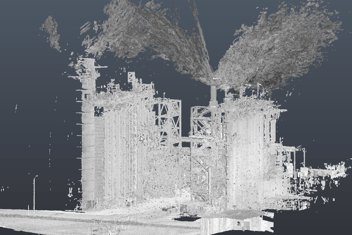
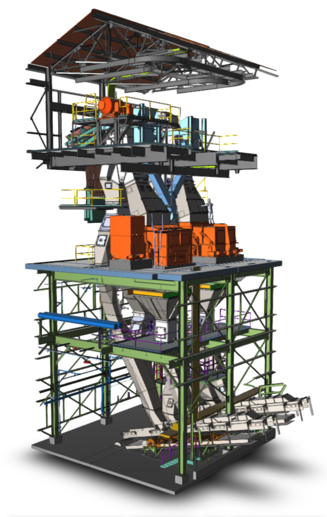
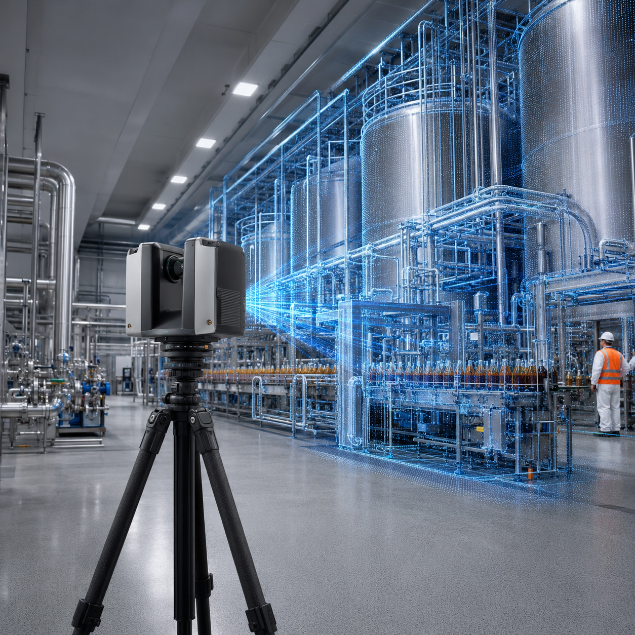
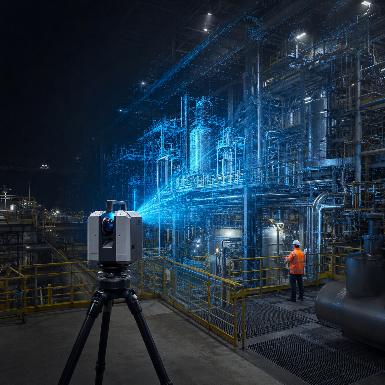
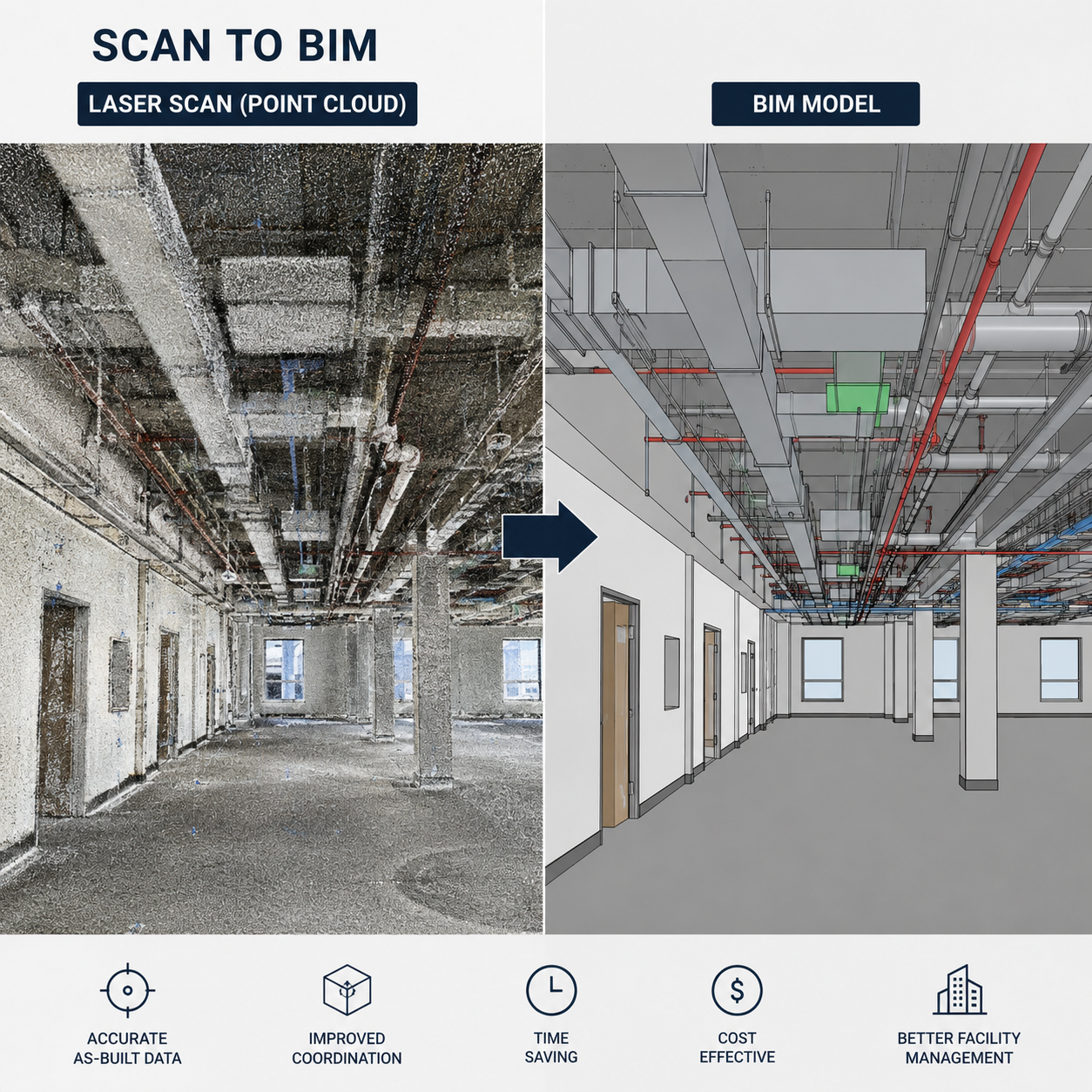
With 3D laser scanning, scan-based modeling, and field-verified documentation, project teams can confirm what is actually in place before the outage begins. Instead of relying on legacy drawings, partial markups, or tribal knowledge, teams can work from current field conditions to validate fit, check clearances, and make fabrication decisions with more confidence.
Most outage problems do not start during the outage. They start weeks earlier, when engineering and planning teams assume the field matches the drawings.
In older or continuously modified facilities, that assumption often fails. Over time, equipment gets shifted, supports are added, valves are changed, piping is rerouted, and steel is modified without every drawing being updated.
For outage planners, plant managers, and EPC teams, that creates familiar risks:
Once the outage clock is running, even a small fit issue can trigger rework, resequencing, extra labor, and lost production time.
Field verification is more than a quick site walk or a few tape measurements.
For complex retrofit scopes, it means capturing the real geometry of the work area and turning it into usable project intelligence. That often includes:
The goal is simple: make sure the planned work will fit the real plant before the outage window begins.
The biggest payoff often comes before anything is built.
When fabrication starts from unverified conditions, every spool, support, frame, or skid carries risk. If one flange is offset, one beam is lower than expected, or one clearance is tighter than shown on the drawings, that problem can ripple through the entire installation sequence.
Using scan-based analysis and verification, teams can answer the questions that matter early:
For outage-driven work, those answers are often the difference between a controlled shutdown and field improvisation.
Consider a common outage-driven retrofit scenario.
A project team needed to prepare a modification in an existing process area with no reliable drawings. The space was dense with structural steel, piping, and operating equipment. The team needed to confirm clearances, validate a tie-in flange location, and gain enough confidence to move forward with fabrication before the outage window.
Rather than relying on incomplete records, the area was laser scanned and modeled around the critical interfaces. That gave the team a way to review the real geometry, verify fit in the congested zone, confirm the tie-in condition, and identify constraints before fabrication release.
The value was not just in producing a model. It was in reducing uncertainty before the shutdown began.
If reliable drawings are missing, these are the highest-value items to verify first.
Tie-ins compress schedule risk into a very small space. If flange orientation, elevation, or centerline location is off, downstream installation work can stall immediately.
Dense steel and equipment layouts create blind spots for design teams working from old drawings. Clearances for access, removal, rigging, and installation should be checked early, especially in brownfield environments.
Retrofit scopes often assume available attachment points, support elevations, or framing geometry that may not be accurate in the field. A scan-based model provides a better basis for support design and constructability review.
Even if the final installed condition works on paper, the component still has to get into place. In outage planning, access constraints can be just as important as final geometry.
Sometimes the biggest problem is not one wrong dimension. It is an incomplete understanding of what actually exists in the area. Accurate 2D as-built drawings and scan-based models create a stronger record for current execution and future work.
Outage confidence is really decision confidence.
When project teams can see verified existing conditions before fabrication and installation begin, they can make better decisions on scope, sequencing, prefabrication, and contingency planning. They are not eliminating every possible risk, but they are removing one of the most common causes of shutdown disruption: starting from bad field information.
That is why reality capture is not just documentation. It is a planning tool.
If the drawings are not trustworthy, the schedule is not either.
Before the outage window opens, verify the existing conditions that matter most. A targeted scan and model of the affected area can give your team the information needed to validate fit, confirm tie-ins, check clearances, and move into fabrication with fewer assumptions.
In shutdown-driven retrofit work, that confidence is often what protects the schedule.
Need confidence before fabrication or shutdown planning advances?
Schedule a retrofit/outage readiness review to define the right scan, modeling, and verification scope for your project.
Each project represents our commitment to accuracy and technical excellence

Talk with our team about your facility, scope, and objectives to determine the right capture, modeling, and analysis approach.