

Industry: Power Generation
Location: Georgia, USA
Project Duration: 4 Months
Facility Area Modeled: 5,000 sq ft Compressor Room

A 2,800 MW coal-fired power plant in Georgia faced a costly engineering problem during a compressed air system upgrade. Newly purchased industrial air dryer equipment valued at over $1 million could not physically fit within the existing compressor room.
Rather than scrap the equipment or undertake expensive infrastructure modifications, the plant leveraged industrial laser scanning and 3D modeling to develop a virtual solution. Using a high-resolution digital twin of the compressor room, engineers tested multiple layout scenarios and optimized piping routes before installation.
The result was a successful retrofit with zero operational downtime, no field rework, and more than $1 million in avoided costs.
Project Impact
The plant had already purchased replacement compressed air dryers as part of a planned system upgrade. During installation planning, engineers discovered a critical issue:
The new dryers had a significantly larger footprint than the equipment they were replacing.
This created a series of major constraints:
Traditional engineering methods would have required extensive field measurements and trial-and-error redesign. With the outage schedule approaching, the plant needed a faster and more reliable approach.
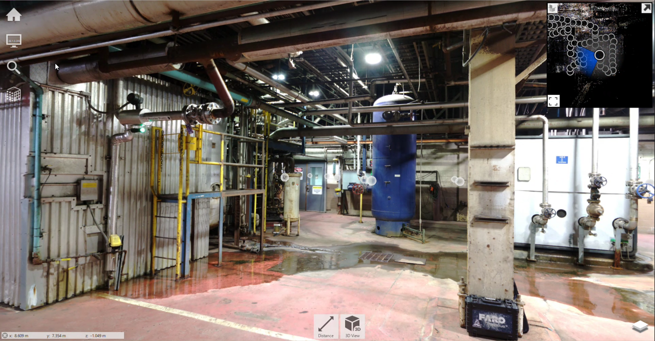
The compressor room presented multiple design challenges that complicated a straightforward equipment replacement:
These conditions made it critical to validate the design before fabrication and installation began.
To solve the problem, AsBuilt created a high-fidelity digital twin of the compressor room using industrial laser scanning and 3D modeling.
Laser scanning captured the existing facility conditions with millimeter-level accuracy, allowing engineers to evaluate spatial constraints and test new equipment configurations virtually.
This digital engineering workflow enabled the team to:
By modeling the system virtually, the engineering team eliminated costly field uncertainty and reduced the risk of installation delays.

The compressor room was scanned using FARO laser scanners, producing an extremely dense point cloud dataset representing the existing facility.
Scanning Specifications
Scanning Technology: FARO laser scanners
Accuracy: 2 mm
Effective Point Spacing: < 1 mm
Data Captured: 20+ billion points
Area Scanned: 5,000 sq ft compressor room
Tall mobile tripods were used to capture difficult-to-reach areas above pipe racks and equipment, ensuring complete spatial coverage of the room.
The resulting point cloud formed the foundation of the project’s digital twin model.
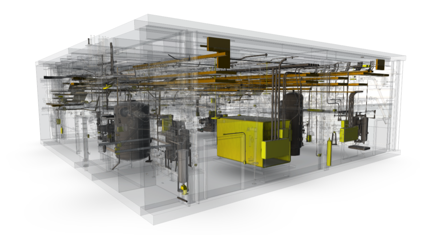
Using the laser scan data, engineers created a detailed 3D model of the compressor room and digitally removed the retiring equipment.
From there, the team tested six different design configurations to determine the most effective layout for the new dryers and associated piping.
Each design iteration evaluated:
A revised Piping and Instrumentation Diagram (P&ID) was developed to capture the functional requirements of the new system before equipment placement was finalized.
This approach ensured that both mechanical layout and operational functionality were addressed simultaneously.
Once the optimal layout was identified, the engineering team generated a comprehensive drawing package to support fabrication and installation.
The design documentation included:
Because the design was validated against the laser scan model, pipe spools could be fabricated in the shop rather than stick builtin the field.
This significantly reduced installation risk and labor costs.
The digital engineering approach produced measurable financial and operational benefits.
Post-installation verification scanning confirmed that the installed system matched the digital design.
The project produced a comprehensive set of engineering deliverables to support installation and long-term plant operations.
Deliverables included:
What initially appeared to be a million-dollar equipment loss became a successful retrofit through the use of laser scanning and digital twin modeling.
By capturing existing conditions with high precision and validating multiple layout scenarios virtually, engineers were able to redesign the system within the available space and eliminate installation uncertainty.
The result was a compressed air system upgrade delivered:
Reality capture and digital twin modeling allow engineers to solve complex retrofit challenges before construction begins.
In this project, virtual design iteration transformed a constrained installation into a predictable, efficient retrofit—saving over $1 million in equipment and construction costs while maintaining uninterrupted plant operations.
Talk with our team about your facility, scope, and objectives to determine the right capture, modeling, and analysis approach.