Fabrication Verification: Crusher Transfer Chute
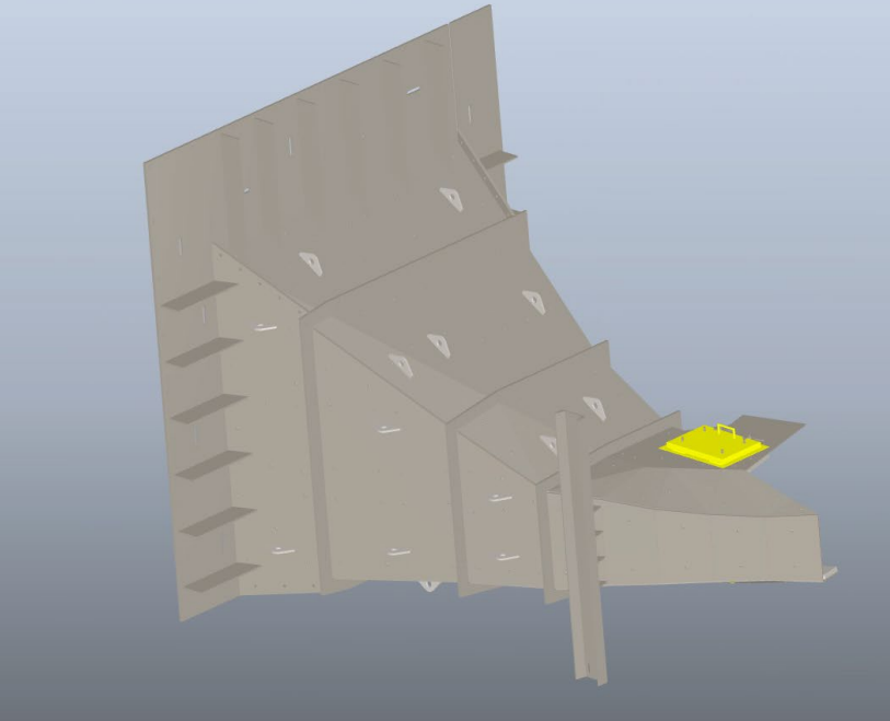
We scanned a fabricated transfer-chute assembly and performed a deviation analysis against the 3D design model to verify fit and identify any issues before shipment. The deliverable: a colorized heat-map showing point-by-point deviations between the laser-scanned point cloud and the design model, plus photoreal walkthroughs of the fabricated parts. See images and heatmap below.
What we did
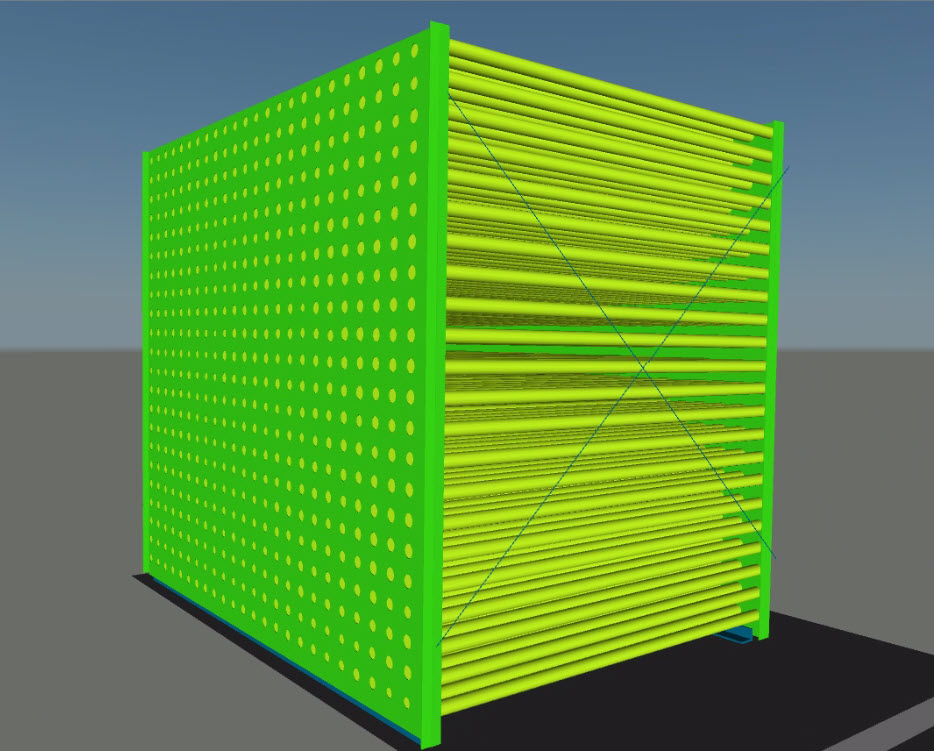
- Captured a high-density laser scan of the as-fabricated assembly and individual components.
- Best-fit aligned the scanned point cloud to the 3D design model.
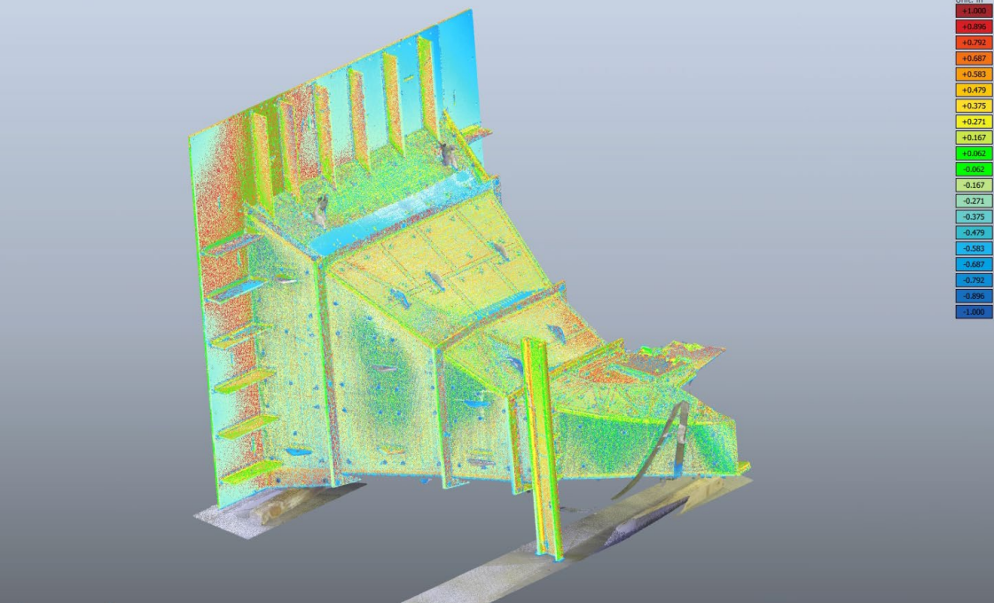
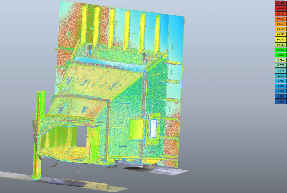
- Generated a deviation heat-map across the assembly and produced close-up imagery for fabrication review.
Deviation analysis legend (how to read the heatmap)
- Green: within ±1/16" tolerance (design intent met).
- Yellow/Light Blue → Dark Blue / Dark Red: increasing deviation up to ±1.00".
- Grey: areas where deviation exceeds ±1.00" or where comparison data is insufficient.
- Values are based on the best-fit registration of the laser-scanned point cloud to the 3D model.

Why this matters
- Bolt-up assurance: Confirms assemblies will bolt up in the field or identifies necessary corrections before shipping.
- Risk reduction: Detects out-of-tolerance conditions early, avoiding on-site rework and schedule delays.
- Actionable QA: Provides engineers and fabricators with precise, localized deviation data for targeted remediation.
Result
- A clear, visual verification that parts met specified tolerance band in critical areas (green zones), with visible outliers highlighted for corrective action. The combined heatmap and photoreal scans enabled the team to approve fit-up or plan fixes before the unit left the shop.
For technical review or to integrate this verification workflow into your fabrication QA/QC, contact AsBuilt.