A major power generation facility relied on a six-floor coal transfer tower to move fuel through one of the most critical points in its material handling system.
The tower supported up to 6,400 tons per hour of coal movement — more than 3,500 pounds per second — and operated up to 20 hours per day during peak summer demand. Approximately 40% of the states electricity flowed through this one tower.
The challenge was not just scale. It was risk.
The legacy transfer arrangement created a single point of failure. Two upper conveyors discharged coal into a shared transfer path. If foreign material entered the chute and caused a plug, coal flow could stop until the obstruction was cleared. At the time the work was conceived, downtime exposure was valued at up to $10,000 per minute.
The project required more than a replacement chute. It required a complete redesign of a mission-critical fuel path, inside an existing tower, within a rare outage window, while protecting long-term throughput reliability.
AsBuilt/Acensium used industrial 3D laser scanning, as-built modeling and design coordination, DEM simulation, fabrication support, and fabrication QA to reduce risk before installation began.
The outcome: a single-failure-point transfer arrangement became a redundant, DEM-validated, scan-verified coal transfer system engineered for fit-up, flow performance, maintainability, and long-term reliability.
Industry: Power Generation
Facility Type: Coal-fired power generation facility
Project Type: Coal transfer tower redesign and retrofit
System Height: Six-floor transfer tower
Material: Coal
System Capacity: Up to 6,400 tons per hour
Operating Demand: Up to 20 hours per day during peak summer demand
Downtime Exposure Basis: Up to $10,000 per minute
Core Technologies: Laser scanning, as-built modeling, 3D engineering, DEM simulation, fabrication QA
Primary Objective: Redesign a critical coal transfer system to reduce plug-related outage exposure, preserve high-volume coal movement, improve material flow, and validate fit-up before installation.
Related service: 3D laser scanning and as-built modeling for industrial facilities
This project was one of the highest-stakes retrofit environments possible.
A major power generation facility needed to replace and redesign a critical coal transfer system inside an existing six-floor tower. The tower moved fuel through a critical point in the plant’s material handling system and supported a substantial share of statewide electricity generation.
The existing arrangement presented a serious operational vulnerability. Multiple conveyors discharged into a common transfer path. If that path plugged, the plant could lose coal flow until the obstruction was cleared. That risk carried a downtime exposure basis of up to $10,000 per minute.
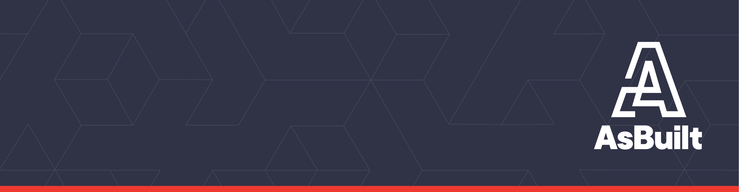
The solution required two new, entirely separate transfer systems within the same existing tower. The new design had to maintain coal flow flexibility, fit around existing beams, conduit, piping, conveyors, and structural steel, and support staged installation in a narrow outage window.
AsBuilt/Acensium engineered the retrofit from laser-scanned as-built data. Every major obstruction was modeled in 3D. DEM simulation was used to validate material flow, center-load receiving belts, reduce freefall, reduce dusting, and limit internal wear. Fabricated chute assemblies were laser scanned before installation to confirm dimensional accuracy and reduce field rework risk.
This was not a conventional design project. It was a full lifecycle risk-reduction effort: capture, design, simulate, fabricate, verify, and install with confidence.
For historical context, an earlier version of this project story was published by Industry Today in “3D Scanning Optimizes Material Handling”.
The transfer tower was not just another structure in the plant. It was a mission-critical fuel-handling asset.
The system could transfer up to 6,400 tons per hour of coal. At that capacity, the tower was moving more than 3,500 pounds of material every second. During peak summer demand, the system operated up to 20 hours per day.
In practical terms, this tower sat at the intersection of fuel reliability, plant uptime, and generation capacity.
Approximately 40% of the states electricity flowed through this one tower. That made the transfer system more than a maintenance concern. It was part of a critical generation pathway.
The legacy transfer arrangement created unacceptable risk. Two conveyors at the top of the tower discharged material into the same orifice and through a system of diverter gates. That material was then routed either to conveyors feeding the boilers or to another conveyor feeding temporary storage.
If foreign objects or oversized material caused the chute to plug, the plant could be “out of business” until the chute was cleared. At the time of project justification, the opportunity cost of that downtime was estimated at up to $10,000 per minute.
That number shaped the entire project.
The engineering work had to reduce exposure to a high-cost outage scenario. The installation had to work inside a limited outage window. The new system had to fit inside an existing tower without creating field surprises. And the material flow had to improve long-term system reliability, not simply replace old steel with new steel.
Related reading: How 3D scanning and as-builts reduce risk in power and utilities
The old transfer system created a single-point-of-failure condition.
Two conveyors loaded material into the same transfer path. From there, diverter gates directed coal toward the boilers or temporary storage. Under normal conditions, the system handled high-volume coal movement. But if a plug occurred in the shared chute path, both the plant’s fuel flow and its operating reliability were exposed.
That created three major problems.
First, the shared path concentrated risk. A blockage in one critical location could interrupt coal flow through the tower.
Second, the old transfer geometry exposed belts and components to high-impact material movement. Coal falling through a transfer system at high volume can damage belts, accelerate component wear, and create dust.
Third, the existing tower was already congested. Any replacement system had to fit around structural steel, conveyors, conduit, pipe, and building constraints that had accumulated over years of plant operation and modification.
This was not an open-field design problem. It was an industrial retrofit inside a dense, existing, multi-level operating environment.

Related project: AsBuilt of a 700-foot underground conveyor
The client needed a retrofit that could be engineered, fabricated, verified, and installed with minimal uncertainty.
That meant solving multiple problems at once.
The new system had to eliminate the shared transfer-path vulnerability by creating two independent material flow paths inside the existing tower. If one path became blocked, the other needed to continue feeding coal to the boilers from the alternate feeding conveyor.
The new chute work also had to support flexible routing. Depending on operating needs, the plant needed to move coal to the boilers, route coal to storage, or split flow through the system.
The new design had to fit inside a six-floor structure already packed with existing equipment. It had to route around beams, conduit, pipes, conveyors, and structural steel. Some chute work would need to clear major obstructions by less than one inch.
The new system also weighed more than the old equipment, which introduced structural loading concerns. Reinforcement steel had to be added, and chute support feet had to land precisely on structural members across multiple levels.
The installation itself added another layer of difficulty. The outage window was limited. Multiple plant systems had to align. The work had to be staged carefully. In a project like this, a missed fit-up, fabrication error, or field interference could consume critical outage time and threaten the entire installation plan.
The project required certainty before the field window opened.
Related service: 3D as-built and design modeling for retrofit planning
The transfer tower presented a rare combination of spatial, operational, structural, and material-flow constraints.
The tower stretched across six floors and contained dense structural steel, conveyors, pipes, conduit, and existing equipment. The new chute work had to be routed through the structure without creating conflicts.
Precision mattered because the clearances were extremely tight. In some locations, the chute work dodged beams and conduit by less than one inch. The two new transfer systems also came extremely close to one another inside the tower.
The transfer tower supported high-volume fuel movement. The plant could not afford extended or unnecessary downtime. The retrofit had to be planned around a narrow outage window, and the installation sequence had to protect the plant’s ability to return to service.
The new chute work was heavier than the system it replaced. This required evaluation of structural loading and the addition of new structural members. Those members had to be inserted into the existing tower, and the support feet on the chute assemblies had to land precisely where designed.
The project was not just about fit-up. Material flow performance had to improve.
Dropping coal too far or too abruptly can damage receiving belts, increase impact loads, create dust, accelerate internal wear, and increase maintenance burden. The new transfer system had to control the material path, slow the coal, support center-loading, and reduce internal wear and dusting.
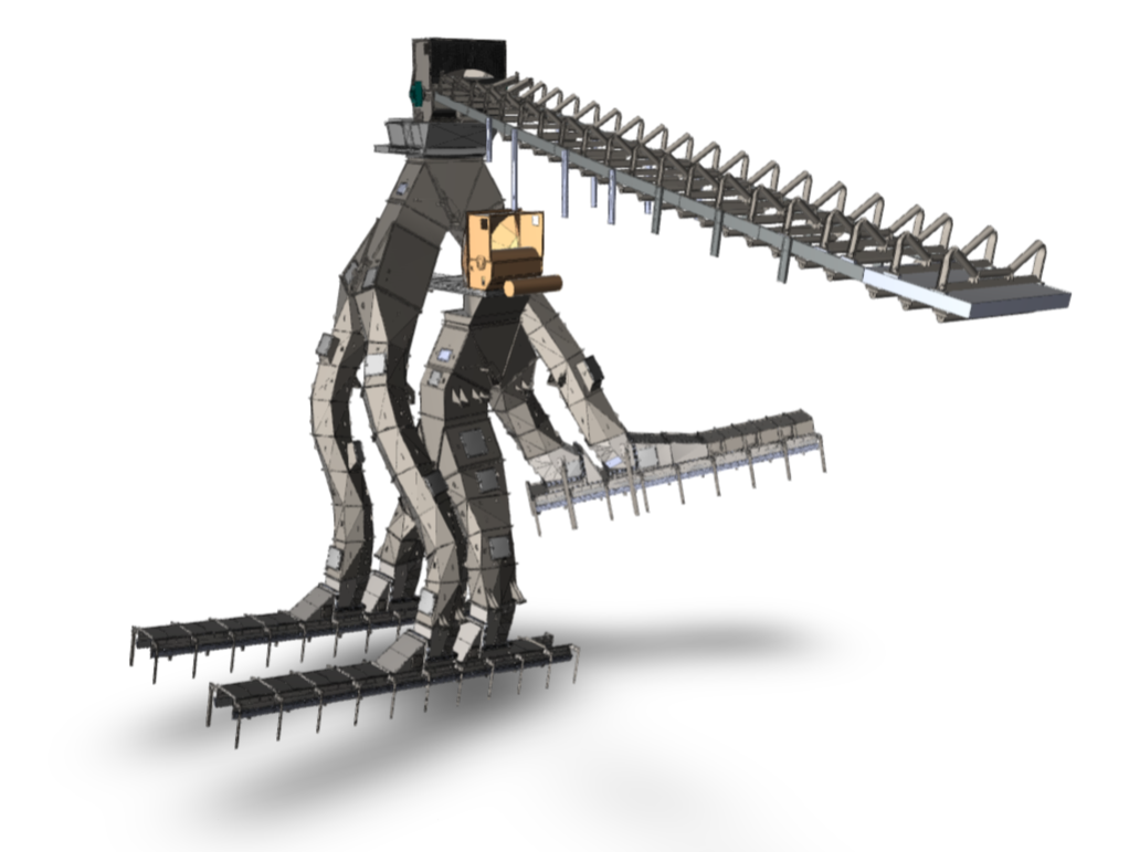
The chute geometry was complex. The plant-selected fabricator was unfamiliar with 3D CAD software and the shapes required by the design. Fabrication support and verification became critical to avoid dimensional errors that would create field-fit problems during installation.
Related case study: Laser scanning and DEM simulation for a crusher feed retrofit
AsBuilt/Acensium started by capturing the tower with industrial 3D laser scanning.
The scan data documented the real-world condition of the tower: beams, pipes, conduit, conveyors, structural steel, equipment, supports, tie-in points, and surrounding obstructions. That information became the foundation for the engineering model.
Instead of designing from assumptions or incomplete legacy drawings, the engineering team designed from verified field conditions.
Every beam, pipe, and conduit was modeled in 3D at its actual location. The chute work was then sized and routed around those conditions to minimize interferences and support installation certainty.
This scan-driven workflow allowed the team to:
The project shifted from reactive field problem-solving to controlled, model-driven execution.
Related service: high-accuracy 3D laser scanning for industrial facilities
The core operating solution was redundancy.
The old system routed material through a shared transfer path. The new design created two entirely separate transfer systems inside the same building. That meant if one side plugged, the other could continue feeding coal to the boilers from the alternate feeding conveyor.
This was a major redesign of the transfer architecture.
The system had to accommodate multiple routing options. Coal could be routed toward the plant, toward the stockpile, or split depending on operating requirements. The arrangement required diverter gates, splitter gates, load zones, and carefully coordinated chute geometry.
The design also supported staged installation. By creating separate systems and multiple load zones, portions of the old system could be removed and replaced while other parts of the plant’s coal-handling operation remained available.
This was one of the most important project outcomes. The design did not simply replace a chute. It reduced the operational vulnerability of a critical fuel path.
Related company background: Acensium engineering services and 3D scanning expertise
A successful transfer chute has to do more than connect one conveyor to another.
At 6,400 tons per hour, coal flow behavior matters. If material drops too far or impacts too aggressively, the result can be belt damage, component wear, dusting, material buildup, poor loading, and reduced system reliability.
AsBuilt/Acensium used Rocky DEM flow simulation to predict how coal would move through the redesigned chute system.
Discrete Element Modeling simulates the physics of individual particles based on material properties. In this project, DEM simulation was used to predict material path, support center-loading of receiving belts, and reduce internal wear and dusting.
The engineering goal was to move coal away from uncontrolled drop-and-impact behavior and into controlled sliding flow.
By shaping the chute geometry carefully, the system slowed the material and directed it through the transfer path more predictably. Instead of falling freely and striking belts or internal components, the coal flowed down engineered surfaces in a more controlled way.
This improved the transfer system in several ways:
Ceramic-lined wear surfaces were incorporated to support long-term performance in an abrasive coal-handling environment. Ceramic is highly resistant to abrasion, but it performs best when the system reduces direct impact. That made the controlled sliding-flow design especially important.
Related case study: Laser scanning and DEM simulation improved crusher feed retrofit performance
The fabrication phase created another major risk point.
The design included complex chute geometry and diverter gate assemblies. The plant-selected fabricator was not accustomed to working with 3D CAD models and shapes of this complexity.
AsBuilt/Acensium supported the fabricator through the process to help ensure that dimensionally accurate chute-work and diverter gate assemblies were produced.
But support alone was not enough. The team also verified the fabricated assemblies with 3D laser scanning before installation.
This fabrication QA step was critical.
The fabricated equipment was laser scanned in the shop to confirm that the assemblies matched the design requirements. This helped ensure fit-up during installation inside the tower.
Without that verification, a dimensional error could have remained hidden until the equipment arrived at the plant. In a narrow outage window, that kind of error could create field rework, installation delays, added cost, and operational risk.
Laser scanning moved the risk upstream.
Instead of discovering fit problems during installation, the team validated dimensional accuracy before field delivery.
Related service: AsBuilt 3D laser scanning and modeling services
The project also required functional validation of hydraulic gate systems.
The diverter gates had to handle high tonnages and operate reliably in the field. Hydraulic cylinder sizes and pressure requirements were engineered to support the required material handling loads.
Before installation, the cylinders were actuated in the fabricator’s shop to validate functionality.
This was another example of the project’s risk-reduction approach. The team was not waiting until field installation to discover whether critical components would function. Fit, fabrication accuracy, and gate operation were all evaluated before the system reached the tower.
Related Acensium reference: Acensium heavy industrial engineering services
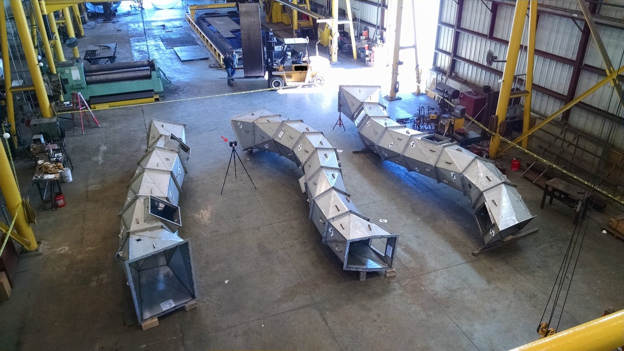
Following fabrication and verification, the new equipment was taken to the plant to replace the old system.
The installation photos show why laser scanning was critical.
The chute work had to fit through a dense existing structure with extremely tight clearances. In some areas, the chute work cleared beams and conduit by less than one inch. The two new transfer systems also passed very close to one another.
The structural installation was also complex. Because the new chute work was heavier than the old equipment, the tower required reinforcement. Siding was removed from the building so new structural members could be inserted. Beams were slid into the tower and connected to support the new system.
The chute assemblies included support feet that had to land precisely on structural members across the tower. A small dimensional error in the model, fabrication, or installation plan could have become a major field problem.
The scan-driven model, fabrication verification, and installation planning helped reduce that risk.
Related project category: AsBuilt industrial laser scanning and modeling project examples
The legacy transfer arrangement created a high-cost outage scenario. If the shared chute plugged, coal flow could be interrupted until the obstruction was cleared. The downtime exposure basis used during project justification was up to $10,000 per minute.
The redesigned system reduced that exposure by replacing the shared transfer path with two independent systems.
This did not just solve a design problem. It reduced the operational vulnerability of a critical fuel path.
The old system routed multiple conveyors through a shared transfer arrangement. That meant one blockage could create broad operational consequences.
The new design created two independent transfer systems within the existing tower. If one transfer path became blocked, the other could continue feeding coal to the boilers from the alternate feeding conveyor.
That redundancy changed the operating architecture of the tower.
The retrofit required precise execution inside a limited outage window. Multiple systems had to align, and the work had to be completed without wasting the opportunity.
Scan-driven engineering, fabrication verification, and installation planning reduced the risk of losing that window to field measurement errors, fabrication issues, or fit-up surprises.
The tower supported up to 6,400 tons per hour of coal transfer. The retrofit preserved that high-volume throughput requirement while improving routing flexibility, redundancy, and long-term maintainability.
The result was not simply a new chute. It was a more reliable transfer system for a mission-critical high-capacity fuel path.
DEM-informed chute geometry slowed coal from uncontrolled freefall into controlled sliding flow.
That reduced belt impact, dusting, and internal wear while supporting longer useful life through ceramic-lined wear surfaces.
The result was a system engineered for performance, not just physical fit.
Fabricated chute assemblies were laser scanned before installation to confirm dimensional accuracy.
Routing, support points, and clearances were validated before field work began. This was especially important in a tower where some clearances were less than one inch.
The project reduced the risk of discovering fabrication or fit-up issues during the outage window.
Industrial retrofits fail when teams rely on assumptions.
Existing facilities rarely match old drawings perfectly. Structural steel gets modified. Conduit gets rerouted. Equipment gets replaced. Access changes. Clearances shrink. In a dense transfer tower, those realities can turn a straightforward-looking replacement into a field problem.
This project demonstrates why scan-driven engineering matters in high-consequence industrial environments.
Laser scanning provided accurate existing-condition data. As-built modeling turned that data into an engineering foundation. DEM simulation improved material-flow performance. Fabrication QA verified the physical system before it reached the field. Installation planning reduced outage-window risk.
Together, those steps created a predictable retrofit process in a setting where guesswork was unacceptable.
For power generation facilities, mining operations, ports, bulk terminals, cement plants, steel mills, and other heavy industrial sites, the lesson is direct:
When throughput, downtime, and safety matter, retrofit design should start with verified field conditions.
Related reading: industrial 3D laser scanning and modeling services
A high-consequence, single-point-of-failure fuel path became a redundant, DEM-validated, scan-verified transfer system.
AsBuilt/Acensium reduced risk across the full project lifecycle:
The project protected a rare outage window, reduced plug-related downtime exposure, preserved high-volume coal transfer, improved material flow, and verified fabrication accuracy before installation.
No guesswork. No lost outage window. No field surprises.
AsBuilt helps industrial teams reduce field uncertainty before the outage window opens. Our laser scanning, as-built modeling, engineering coordination, DEM simulation, and fabrication QA workflows help owners, engineers, and contractors validate complex retrofit work before it reaches the field.
Talk to AsBuilt about your next retrofit.
Scan-driven engineering uses 3D laser scanning to capture existing facility conditions and convert those conditions into accurate models for design, coordination, fabrication, and installation planning.
Laser scanning helps reduce field uncertainty by documenting the actual location of beams, pipes, conduit, equipment, and structural elements. This is critical when new equipment must fit inside congested existing facilities.
Learn more about 3D laser scanning services for industrial facilities.
DEM, or Discrete Element Modeling, simulates the movement of individual particles through a material handling system. It is used to evaluate flow behavior, transfer chute geometry, belt loading, dusting, and internal wear.
DEM simulation helps engineers understand how coal will move through a chute before it is built. This allows the chute geometry to be adjusted to reduce freefall, control impact, improve belt loading, reduce dust, and reduce internal wear.
Fabrication QA laser scanning verifies that fabricated assemblies match design requirements before they are delivered to the field. This reduces the risk of discovering dimensional errors during installation.
During outage work, field rework can create expensive delays. Verifying fabricated equipment before installation helps protect the outage window and reduce the likelihood of fit-up surprises.
The project involved a six-floor transfer tower, high coal throughput, a shared-path plug risk, tight existing conditions, sub-inch clearances, structural reinforcement, complex chute geometry, and a limited installation window.
The main outcome was converting a vulnerable shared transfer path into two independent transfer systems, while using laser scanning, DEM simulation, and fabrication QA to reduce installation and operational risk.
Related case study: Laser scanning and DEM simulation for crusher feed retrofit performance
Talk with our team about your facility, scope, and objectives to determine the right capture, modeling, and analysis approach.