
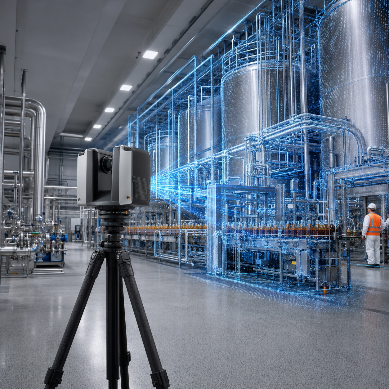
Most guidance about industrial as-built documentation is written with a refinery or a power plant in the background. Big, congested, dirty, and shut down on a predictable cycle that everyone plans a year around.
Food and beverage plants break several of those assumptions at once. They change more often than heavy industry does, they stop for less time, and they are subject to constraints — washdown, sanitary zoning, allergen segregation, product safety — that shape what a project team is even allowed to do in the space.
The result is a facility type where accurate existing-condition data is unusually valuable and unusually hard to collect on a normal schedule. Here is what makes it different and what to do about it when you scope the work.
Every operating facility outruns its drawings. F&B plants do it faster, for structural reasons rather than sloppy ones.
Lines change with the product. A new SKU, a new pack format, a new closure, a seasonal run — each can move equipment, add a conveyor, reroute a utility, or reconfigure a packaging end. These are frequent, relatively small changes, and small changes are precisely the ones that never make it back into a drawing set. Nobody redlines a floor plan for a conveyor extension.
Utilities accumulate. Process water, CIP supply and return, compressed air, steam, refrigerant, drain, and electrical get added incrementally over years. Overhead space in a mature plant is a record of every project that ever happened there, and almost none of it is documented in a form anyone can use.
Ownership and contractors turn over. Plants change hands, integrators come and go, and drawing sets get inherited rather than maintained. The set that exists is frequently the original construction set with a decade of undocumented modification behind it.
None of this is a criticism of the maintenance organization. It is what happens when a facility runs continuously and changes constantly. But it means that when a real project arrives — a line expansion, an equipment replacement, an automation retrofit, a refrigeration upgrade — the drawings are a starting hypothesis, not a basis.
Four features of the environment change how the work has to be done. Each one has scoping consequences.
Production almost never stops. Many F&B plants run continuously, or close to it, with sanitation windows measured in hours rather than days. There is no annual outage to attach the work to. Capture has to happen around production, in short defined windows, often at night or between changeovers, and often in pieces.
The consequence: plan for fragmented access from the start. Fragmented capture is more expensive than continuous capture, but it is far less expensive than a mobilization that arrives assuming continuous access and does not get it.
Sanitary zoning limits movement. Equipment, footwear, and personnel cannot always move freely between zones. High-care and low-care areas may require separate access procedures, dedicated equipment, or specific hygiene protocols. A crew that has to change over between zones loses productive hours to it, and equipment that has to be wiped down or dedicated to a zone changes the logistics.
The consequence: name the zoning in the scope, not at the gate. Zone rules discovered on the first morning become schedule.
Washdown and wet conditions. Areas subject to washdown constrain when work can happen and what condition surfaces are in. Wet floors, condensation, steam, and residual moisture affect both safety and, in some conditions, capture quality on reflective stainless surfaces.
The consequence: schedule capture relative to the sanitation cycle rather than to the clock.
Congested interstitial space. The zone above the ceiling or between floors in a processing area is where the utilities live, and it is typically the least documented and most congested part of the building. It is also where most retrofit conflicts occur, because that is where new services have to route.
The consequence: decide explicitly whether interstitial space is in scope. It is frequently the highest-value area to capture and the one most often left out of a scope written from a floor plan.
The general rule holds here: accuracy is set by the tightest fit-up someone will attempt from the model, and it should be specified per element rather than across the facility. The full framework is in what accuracy does your as-built model actually need.
Applied to a typical F&B project, that usually sorts into three bands.
Layout and clearance questions — will the new filler fit, does the case packer clear the column, can the pallet path work — are centimeter-scale questions. They need reliable geometry and reliable registration, not fabrication tolerance.
Routing of new utilities through existing interstitial space needs tighter data, because the whole point is threading new services through a congested zone without a field conflict.
Tie-ins and connection interfaces — where new process piping meets existing, where a skid lands on existing steel, where a drain connects — are the tight elements, and there are usually few of them. Specify those separately and let the rest be what it needs to be.
Spending fabrication tolerance on a whole processing hall is the most common way to make an F&B quote look unaffordable.
Worth being concrete about what the documentation gets used for, because that determines the scope.
Line expansion and reconfiguration. The most common driver. Will the new equipment fit, what has to move, what clearances are lost, and can the change be installed in the windows available.
Equipment replacement. Filler, palletizer, oven, chiller, pump skid. The fit questions are dimensional and the removal path frequently matters more than the installation path, because the building has been built around the existing unit.
Utility and refrigeration upgrades. Routing new services through interstitial space that is not documented. This is where an accurate model saves the most rework, and where the absence of one produces the most field conflicts.
Automation and controls retrofits. Cable tray routing, panel locations, sensor and device placement, and the physical space for all of it.
Coordination between trades. When mechanical, electrical, and process contractors are working in the same congested zone, a shared verified model is the thing that stops three trades from designing into the same cubic metre. That is a BIM coordination workflow, and it depends entirely on the existing-condition model being right.
Facility records and change management. A current model as the baseline for what is actually installed, updated as modifications happen, so the next project does not start from the same guesswork.
Six things worth putting in a request for this facility type, beyond the general advice in how to write a scan-to-BIM RFP:
One more, less a specification than a scheduling habit: capture the whole area while you are mobilized, even if you only need to model part of it now. In a plant with hourly access windows, remobilization is the expensive step. The field data is the part you cannot get back later without paying for access twice.
Reality capture in a food and beverage plant is not technically harder than in heavy industry. The instruments are the same and the modeling is the same.
What is different is that the constraints are operational rather than mechanical — windows, zoning, hygiene, changeovers — and those constraints have to be designed into the scope rather than discovered during it. A scope written from a floor plan will meet all four of them on the first morning. A scope written from the plant's actual operating rhythm gets the same data for less money and less disruption.
Planning a line change or an equipment swap? Tell us the window, the zoning, and what you will be building from the model, and we will scope the capture around your production rather than against it. Get a quote →
Related reading: What accuracy does your as-built model actually need · How to write a scan-to-BIM RFP · Industries we serve

Each project represents our commitment to accuracy and technical excellence


Talk with our team about your facility, scope, and objectives to determine the right capture, modeling, and analysis approach.